Technical Drawing Symbols
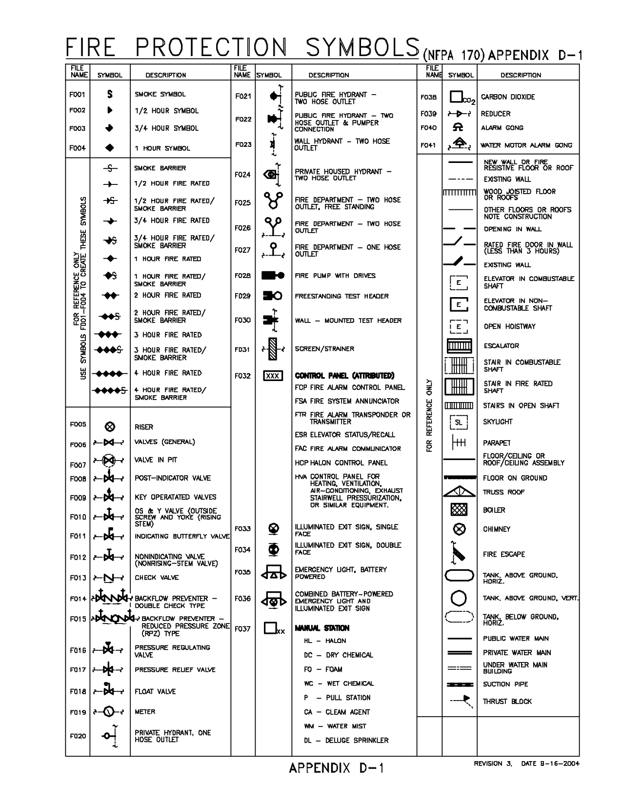
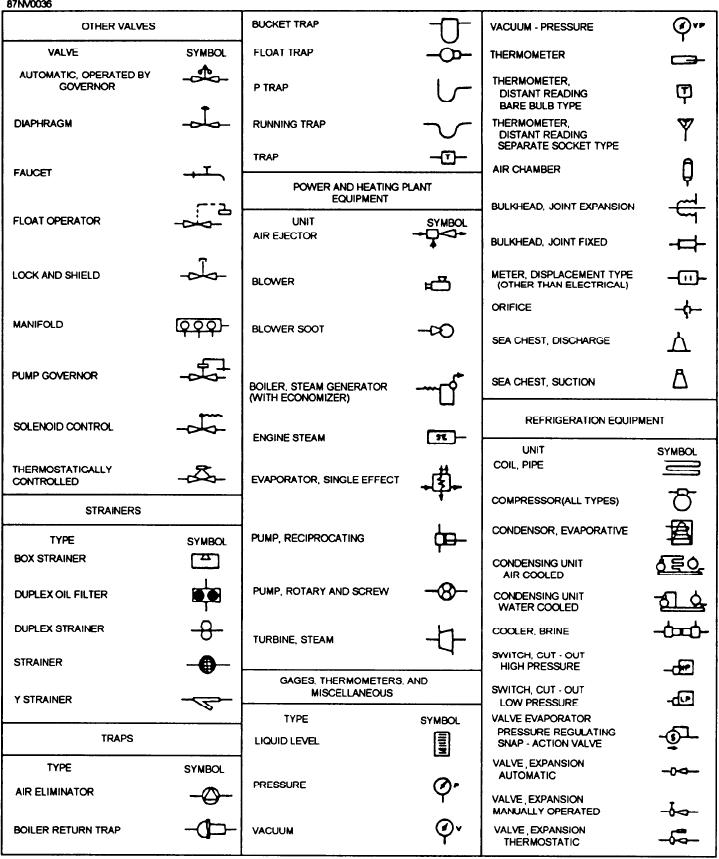
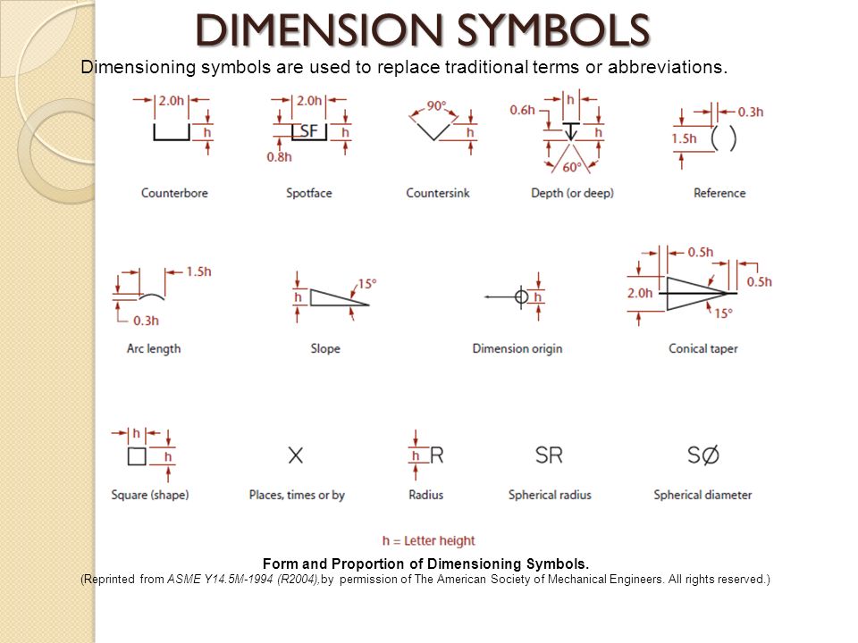
Technical Drawing Symbols - Surface symbols in technical drawings: Milestone plm solutions offers cad, cam & fea services for. Basic types of symbols used in engineering drawings are countersink, counterbore, spotface, depth, radius,. Engineering drawings are the industry's means of communicating detailed and accurate information on how to fabricate, assemble, troubleshoot, repair, and operate a piece of. Review line types and weights, and interpret technical drawing symbols. The basic symbol types used in engineering drawings are diameter, depth, radius, counterbore, spotface, and countersink. The following is a list of symbols that are commonly found in engineering drawings: This document defines and provides examples of common technical drawing symbols used in engineering drawings including straightness, flatness, circularity, cylindricity, profile of a line,. Find the list of standard technical engineering drawing symbols and design elements for cnc manufacturing. 262 rows learn the meaning and usage of common symbols and terms on engineering. Basic types of symbols used in engineering drawings are countersink, counterbore, spotface, depth, radius,. Learn how to create and use geometric dimensioning and tolerancing symbols, common architectural symbols, piping symbols, and electrical symbols in autocad. Technical drawings are graphic representations of objects or concepts that use a universal language of graphic. Engineering drawings are the industry's means of communicating detailed and accurate information on how to fabricate, assemble, troubleshoot, repair, and operate a piece of. Engineering drawing abbreviations and symbols are used to communicate and detail the characteristics of an engineering drawing. Learn the meaning and usage of common engineering drawing abbreviations and symbols, such as kg, cm, cyl, equi sp, and more. Review line types and weights, and interpret technical drawing symbols. Indicates a machining operation or process. The basic symbol types used in engineering drawings are diameter, depth, radius, counterbore, spotface, and countersink. Find out the meaning and function of different symbols, lines,. Learn how to create and use geometric dimensioning and tolerancing symbols, common architectural symbols, piping symbols, and electrical symbols in autocad. Represents a hole or drilled feature. Basic types of symbols used in engineering drawings are countersink, counterbore, spotface, depth, radius,. Learn the meaning and usage of common engineering drawing abbreviations and symbols, such as kg, cm, cyl, equi sp,. Represents a hole or drilled feature. Engineering drawings are the industry's means of communicating detailed and accurate information on how to fabricate, assemble, troubleshoot, repair, and operate a piece of. Milestone plm solutions offers cad, cam & fea services for. This list includes abbreviations common to the. Indicates a machining operation or process. Find the list of standard technical engineering drawing symbols and design elements for cnc manufacturing. Basic types of symbols used in engineering drawings are countersink, counterbore, spotface, depth, radius,. Here is a chart type featuring some commonly used engineering drawing symbols: Technical drawings are graphic representations of objects or concepts that use a universal language of graphic. Learn the basics. The basic symbol types used in engineering drawings are diameter, depth, radius, counterbore, spotface, and countersink. Technical drawings are graphic representations of objects or concepts that use a universal language of graphic. Represents a hole or drilled feature. Find the list of standard technical engineering drawing symbols and design elements for cnc manufacturing. Find common gd&t symbol examples in charts. Learn how to create and use geometric dimensioning and tolerancing symbols, common architectural symbols, piping symbols, and electrical symbols in autocad. 262 rows learn the meaning and usage of common symbols and terms on engineering. Engineering drawings are the industry's means of communicating detailed and accurate information on how to fabricate, assemble, troubleshoot, repair, and operate a piece of. Review. Engineering drawing abbreviations and symbols are used to communicate and detail the characteristics of an engineering drawing. Find the list of standard technical engineering drawing symbols and design elements for cnc manufacturing. Engineering drawings are the industry's means of communicating detailed and accurate information on how to fabricate, assemble, troubleshoot, repair, and operate a piece of. Learn how to create. Engineering drawings are the industry's means of communicating detailed and accurate information on how to fabricate, assemble, troubleshoot, repair, and operate a piece of. Learn how to create and use geometric dimensioning and tolerancing symbols, common architectural symbols, piping symbols, and electrical symbols in autocad. Find common gd&t symbol examples in charts broken down by their use in drawing &. Indicates a machining operation or process. Here is a chart type featuring some commonly used engineering drawing symbols: The basic symbol types used in engineering drawings are diameter, depth, radius, counterbore, spotface, and countersink. This document defines and provides examples of common technical drawing symbols used in engineering drawings including straightness, flatness, circularity, cylindricity, profile of a line,. Engineering drawings. Engineering drawing abbreviations and symbols are used to communicate and detail the characteristics of an engineering drawing. Basic types of symbols used in engineering drawings are countersink, counterbore, spotface, depth, radius,. Surface symbols in technical drawings: The basic symbol types used in engineering drawings are diameter, depth, radius, counterbore, spotface, and countersink. This document defines and provides examples of common. Technical drawings are graphic representations of objects or concepts that use a universal language of graphic. Find the list of standard technical engineering drawing symbols and design elements for cnc manufacturing. The basic symbol types used in engineering drawings are diameter, depth, radius, counterbore, spotface, and countersink. Find out the meaning and function of different symbols, lines,. Learn how to. Find the list of standard technical engineering drawing symbols and design elements for cnc manufacturing. Engineering drawings are the industry's means of communicating detailed and accurate information on how to fabricate, assemble, troubleshoot, repair, and operate a piece of. Learn the basics of how to read engineering drawing symbols for pfds, p&ids, and mechanical engineering. Find out the meaning and function of different symbols, lines,. Review line types and weights, and interpret technical drawing symbols. The following is a list of symbols that are commonly found in engineering drawings: Learn the meanings and uses of various symbols on engineering drawings, such as gd&t, piping, electrical, and structural. Find common gd&t symbol examples in charts broken down by their use in drawing & drafting. Surface symbols in technical drawings: The basic symbol types used in engineering drawings are diameter, depth, radius, counterbore, spotface, and countersink. 262 rows learn the meaning and usage of common symbols and terms on engineering. Basic types of symbols used in engineering drawings are countersink, counterbore, spotface, depth, radius,. Engineering drawings are the industry's means of communicating detailed and accurate information on how to fabricate, assemble, troubleshoot, repair, and operate a piece of. Engineering drawing abbreviations and symbols are used to communicate and detail the characteristics of an engineering drawing. Here is a chart type featuring some commonly used engineering drawing symbols: Learn the meaning and usage of common engineering drawing abbreviations and symbols, such as kg, cm, cyl, equi sp, and more.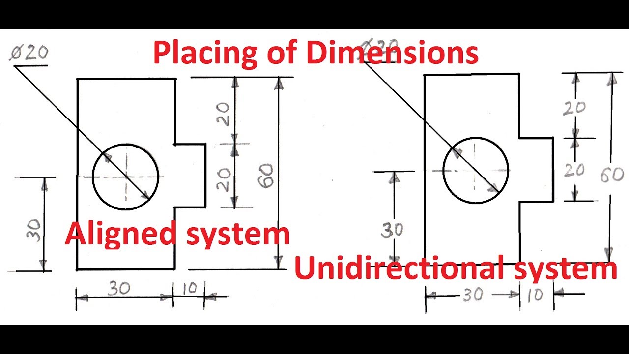
Technical Drawing Symbols The Best Porn Website

鍔 Klarheit Luft technical drawing symbols Geisel Harmonie Hat verloren

Standard Architectural Drawing Symbols
Drawing Symbols In Technical Drawing
Engineering Drawing Symbols

Asme Drawing Symbols
Structural Drawing Symbols

Mechanical Technical Drawing Symbols

Standard Architectural Drawing Symbols
Technical Drawing Dimension Symbols Design Talk
Indicates A Machining Operation Or Process.
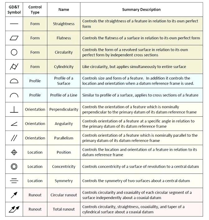
This Document Defines And Provides Examples Of Common Technical Drawing Symbols Used In Engineering Drawings Including Straightness, Flatness, Circularity, Cylindricity, Profile Of A Line,.
Represents A Hole Or Drilled Feature.
Technical Drawings Are Graphic Representations Of Objects Or Concepts That Use A Universal Language Of Graphic.
Related Post: