Symbols In Mechanical Drawing
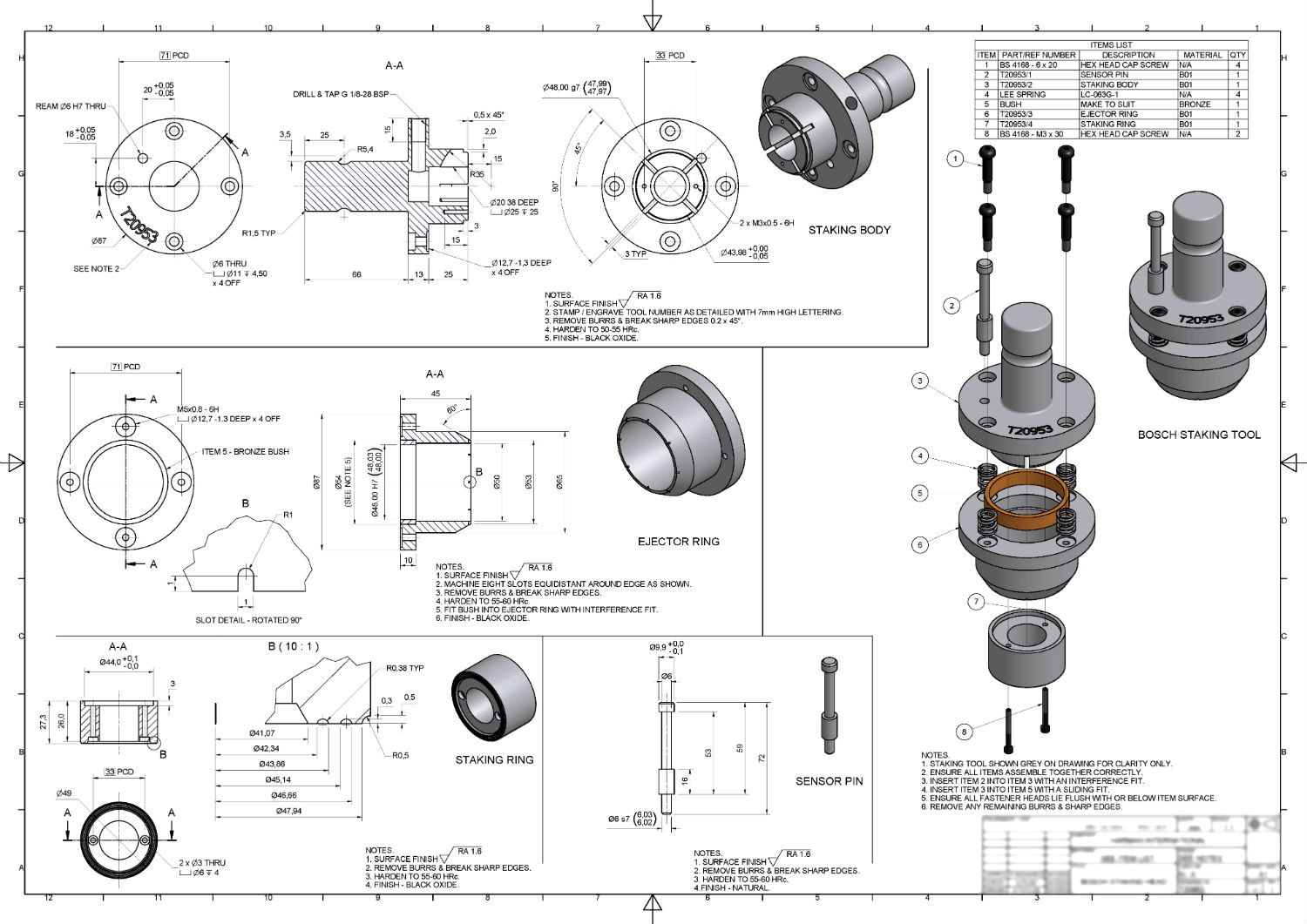
Symbols In Mechanical Drawing - Indicates a machining operation or process. They represent components, elements, details, characteristics, actions, features, and conditions. Represents a hole or drilled feature. Symbols in mechanical drawings are graphical elements accepted by standards and codes. This list includes abbreviations common to the. We will cover symbols for geometric shapes, dimensions and tolerances,. Engineering drawings are the industry's means of communicating detailed and accurate information on how to fabricate, assemble, troubleshoot, repair, and operate a piece of. The figure shows the layout of a typical sheet, showing the drawing frame, a typical title block,. These symbols and abbreviations are. Mechanical drawing symbols are standardized graphical representations used on blueprints to indicate the geometry and function of items within a system. The following is a short list of symbols that normally appear on a technical drawing and need understanding. Symbols for materials and dimensioning play a crucial role in conveying precise design specifications and requirements in mechanical engineering drawings. Represents a hole or drilled feature. Drafting symbols symbols provide a “common language” for drafters all over the world. This guide offers a comprehensive overview of the most common symbols used in technical drawings, spanning multiple disciplines including mechanical, electrical, and architectural. We will cover symbols for geometric shapes, dimensions and tolerances,. In this article, we will provide an overview of common symbols and abbreviations used in mechanical design. Here is a chart type featuring some commonly used engineering drawing symbols: They represent components, elements, details, characteristics, actions, features, and conditions. Some symbols are defined in an equipment. These abbreviations can be found on engineering drawings such as mechanical, electrical, piping and plumbing, civil, and structural drawings. Here are more commonly used engineering drawing. Discover the key ansi mechanical drawing symbols, their meanings, and how they simplify communication in technical design and manufacturing processes. We offer you our tips which we believe are useful for dispelling uncertainty by.. Use of standardized and recognized mechanical vector symbols helps you design understandable mechanical drawings, diagrams and mechanical engineering schematics. Drafting symbols symbols provide a “common language” for drafters all over the world. Find common gd&t symbol examples in charts broken down by their use in drawing & drafting. In this comprehensive guide, we will explore the essential symbols on engineering. We will cover symbols for geometric shapes, dimensions and tolerances,. Various symbols and abbreviations in engineering drawings give you information about the dimensions, design, and materials used. These abbreviations can be found on engineering drawings such as mechanical, electrical, piping and plumbing, civil, and structural drawings. Engineering drawings are the industry's means of communicating detailed and accurate information on how. The following is a short list of symbols that normally appear on a technical drawing and need understanding. Symbols for materials and dimensioning play a crucial role in conveying precise design specifications and requirements in mechanical engineering drawings. Here are more commonly used engineering drawing. However, symbols can be meaningful only if they are created according to the relevant standards. This guide offers a comprehensive overview of the most common symbols used in technical drawings, spanning multiple disciplines including mechanical, electrical, and architectural. This list includes abbreviations common to the. In this article, we will provide an overview of common symbols and abbreviations used in mechanical design. Engineering drawing abbreviations and symbols are used to communicate and detail the characteristics. Mechanical drawing symbols are standardized graphical representations used on blueprints to indicate the geometry and function of items within a system. Common abbreviations include ac (alternating. This list includes abbreviations common to the. In this article, we will provide an overview of common symbols and abbreviations used in mechanical design. Symbols for materials and dimensioning play a crucial role in. However, symbols can be meaningful only if they are created according to the relevant standards or. Symbols for materials and dimensioning play a crucial role in conveying precise design specifications and requirements in mechanical engineering drawings. It establishes symbols, rules, definitions, requirements, defaults, and recommended practices for stating and interpreting gd&t and related requirements for use on engineering. In this. We offer you our tips which we believe are useful for dispelling uncertainty by. Common abbreviations include ac (alternating. However, symbols can be meaningful only if they are created according to the relevant standards or. This guide offers a comprehensive overview of the most common symbols used in technical drawings, spanning multiple disciplines including mechanical, electrical, and architectural. The figure. Discover the key ansi mechanical drawing symbols, their meanings, and how they simplify communication in technical design and manufacturing processes. We will cover symbols for geometric shapes, dimensions and tolerances,. Symbols in mechanical drawings are graphical elements accepted by standards and codes. The figure shows the layout of a typical sheet, showing the drawing frame, a typical title block,. Symbols. Engineering drawings are the industry's means of communicating detailed and accurate information on how to fabricate, assemble, troubleshoot, repair, and operate a piece of. They represent components, elements, details, characteristics, actions, features, and conditions. Find common gd&t symbol examples in charts broken down by their use in drawing & drafting. However, symbols can be meaningful only if they are created. Some symbols are defined in an equipment. The following is a short list of symbols that normally appear on a technical drawing and need understanding. These abbreviations can be found on engineering drawings such as mechanical, electrical, piping and plumbing, civil, and structural drawings. Symbols for materials and dimensioning play a crucial role in conveying precise design specifications and requirements in mechanical engineering drawings. Mechanical drawing symbols are standardized graphical representations used on blueprints to indicate the geometry and function of items within a system. Find common gd&t symbol examples in charts broken down by their use in drawing & drafting. Standard layouts of drawing sheets are specified by the various standards organizations. Here are more commonly used engineering drawing. Common abbreviations include ac (alternating. Here is a chart type featuring some commonly used engineering drawing symbols: Indicates a machining operation or process. This list includes abbreviations common to the. Engineering drawings are the industry's means of communicating detailed and accurate information on how to fabricate, assemble, troubleshoot, repair, and operate a piece of. In this article, we will provide an overview of common symbols and abbreviations used in mechanical design. However, symbols can be meaningful only if they are created according to the relevant standards or. Drafting symbols symbols provide a “common language” for drafters all over the world.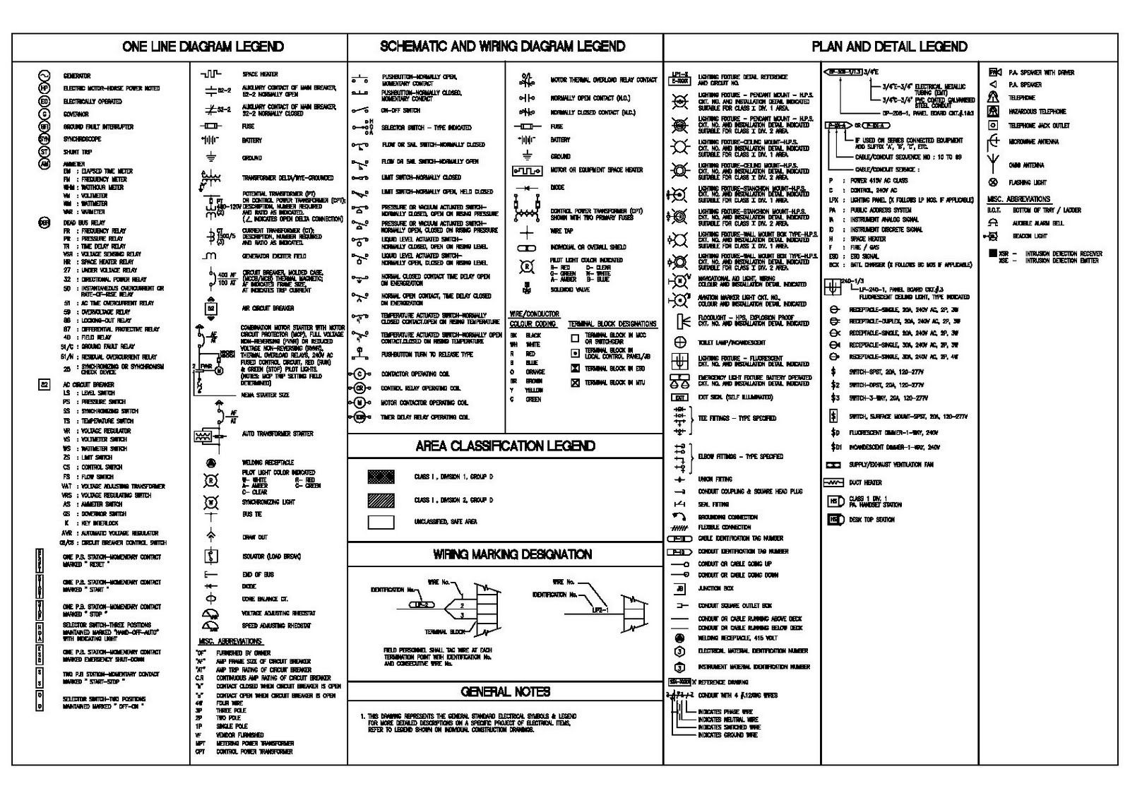
Mechanical Engineering Drawing Symbols Pdf Free Download at
Mechanical Engineering Drawing Symbols Pdf Free Download at
Mechanical Engineering Drawing Symbols Pdf Free Download at

Drawing Symbols Mechanical

how to read mechanical engineering drawing symbols Wiring Work
Mechanical Engineering Drawing Symbols Pdf Free Download at
Mechanical Engineering Drawing Symbols Pdf Free Download at

Mechanical Engineering Drawing Symbols Pdf Free Download at

Mechanical Engineering Drawing Symbols Pdf Free Download at

Mechanical Drawing Symbols from Mechanical Engineering — Welding
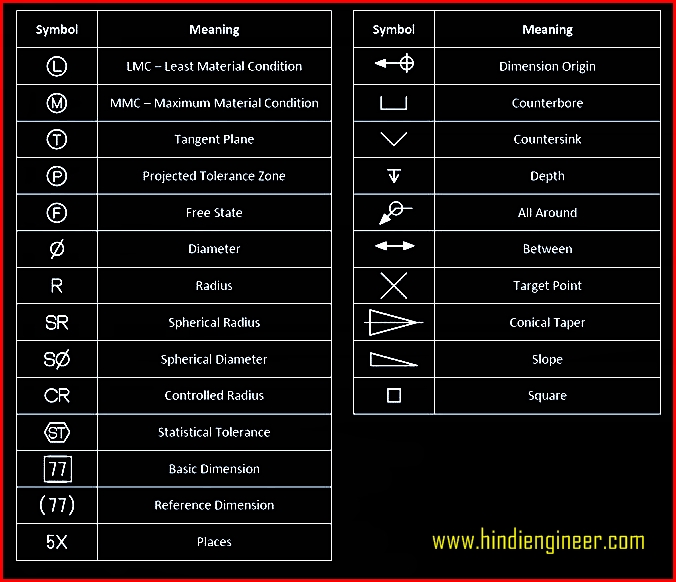
Various Symbols And Abbreviations In Engineering Drawings Give You Information About The Dimensions, Design, And Materials Used.
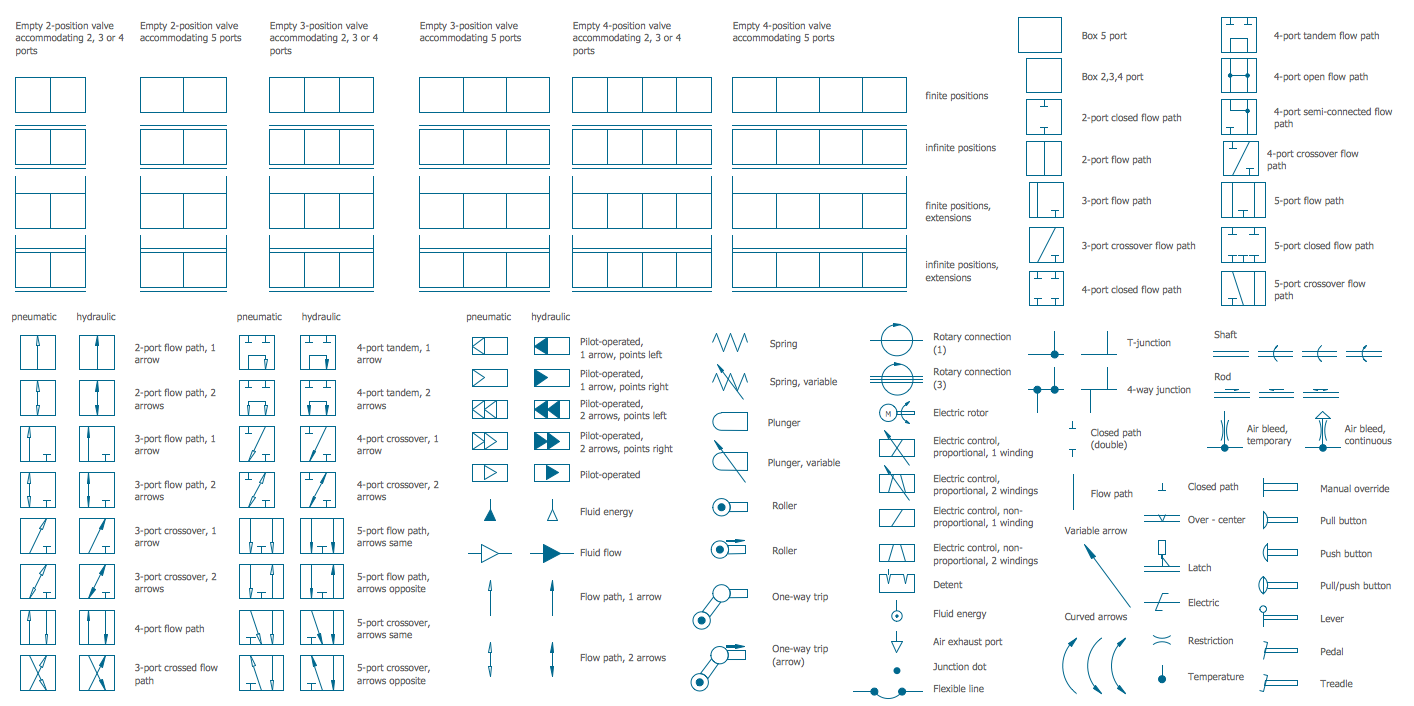
Use Of Standardized And Recognized Mechanical Vector Symbols Helps You Design Understandable Mechanical Drawings, Diagrams And Mechanical Engineering Schematics.
We Offer You Our Tips Which We Believe Are Useful For Dispelling Uncertainty By.
Represents A Hole Or Drilled Feature.
Related Post: