Symbol Mechanical Drawing
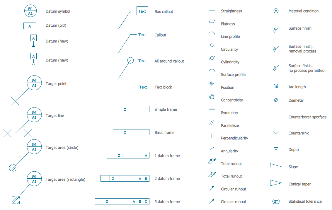
Symbol Mechanical Drawing - From materials and dimensioning to geometric tolerancing, electrical symbols, and fluid power systems, these symbols provide a visual language for engineers to understand and. Here we collected the standard technical engineering drawing abbreviations and symbols to provide help for users. An engineering (or technical) drawingis a. The kennedy space center (ksc) engineering drawing practices, volume i of ii, aerospace and ground support equipment, is the official source for the requirements and interpretations to be. Represents a hole or drilled feature. Mechanical engineering solution — 8 libraries are available with 602 commonly used mechanical drawing symbols in mechanical engineering solution,. Engineering drawings are the industry's means of communicating detailed and accurate information on how to fabricate, assemble, troubleshoot, repair, and operate a piece of. Graphics communications are used in every phase of engineering design starting from concept illustration all the way to the manufacturing phase. General symbols are used with dimensions to clarify the requirement defined by a dimension value and to minimize the number of words or abbreviations placed on a drawing. The following is a short list of symbols that normally appear on a technical drawing and need understanding. We offer you our tips which we believe are useful for dispelling uncertainty by. Here we collected the standard technical engineering drawing abbreviations and symbols to provide help for users. Indicates a machining operation or process. Engineering drawings are the industry's means of communicating detailed and accurate information on how to fabricate, assemble, troubleshoot, repair, and operate a piece of. Here is a chart type featuring some commonly used engineering drawing symbols: An engineering (or technical) drawingis a. Provide separate manufacturer’s construction drawings and calculations that are sealed by the structural engineer of record for the prefabricated metal building. Represents a hole or drilled feature. Newer superseded drawings are listed under superseded construction standard. General symbols are used with dimensions to clarify the requirement defined by a dimension value and to minimize the number of words or abbreviations placed on a drawing. Here is a chart type featuring some commonly used engineering drawing symbols: Newer superseded drawings are listed under superseded construction standard. From materials and dimensioning to geometric tolerancing, electrical symbols, and fluid power systems, these symbols provide a visual language for engineers to understand and. Provide separate manufacturer’s construction drawings and calculations that are sealed by the structural engineer of. The kennedy space center (ksc) engineering drawing practices, volume i of ii, aerospace and ground support equipment, is the official source for the requirements and interpretations to be. Engineering drawings are the industry's means of communicating detailed and accurate information on how to fabricate, assemble, troubleshoot, repair, and operate a piece of. Represents a hole or drilled feature. The included. Here we collected the standard technical engineering drawing abbreviations and symbols to provide help for users. Construction standard drawings that have been updated or deleted before may 2012 are listed below. From materials and dimensioning to geometric tolerancing, electrical symbols, and fluid power systems, these symbols provide a visual language for engineers to understand and. The included collection of predesigned. Here we collected the standard technical engineering drawing abbreviations and symbols to provide help for users. Newer superseded drawings are listed under superseded construction standard. The kennedy space center (ksc) engineering drawing practices, volume i of ii, aerospace and ground support equipment, is the official source for the requirements and interpretations to be. General symbols are used with dimensions to. From materials and dimensioning to geometric tolerancing, electrical symbols, and fluid power systems, these symbols provide a visual language for engineers to understand and. Provide separate manufacturer’s construction drawings and calculations that are sealed by the structural engineer of record for the prefabricated metal building. The included collection of predesigned mechanical drafting symbols, machining drawing symbols, and machinist symbols helps. Graphics communications are used in every phase of engineering design starting from concept illustration all the way to the manufacturing phase. Here we collected the standard technical engineering drawing abbreviations and symbols to provide help for users. However, symbols can be meaningful only if they are created according to the relevant standards or. The following is a short list of. Construction standard drawings that have been updated or deleted before may 2012 are listed below. An engineering (or technical) drawingis a. Provide separate manufacturer’s construction drawings and calculations that are sealed by the structural engineer of record for the prefabricated metal building. The following is a short list of symbols that normally appear on a technical drawing and need understanding.. Drafting symbols symbols provide a “common language” for drafters all over the world. The following is a short list of symbols that normally appear on a technical drawing and need understanding. General symbols are used with dimensions to clarify the requirement defined by a dimension value and to minimize the number of words or abbreviations placed on a drawing. However,. Graphics communications are used in every phase of engineering design starting from concept illustration all the way to the manufacturing phase. Newer superseded drawings are listed under superseded construction standard. However, symbols can be meaningful only if they are created according to the relevant standards or. Here is a chart type featuring some commonly used engineering drawing symbols: General symbols. An engineering (or technical) drawingis a. Here we collected the standard technical engineering drawing abbreviations and symbols to provide help for users. Newer superseded drawings are listed under superseded construction standard. Graphics communications are used in every phase of engineering design starting from concept illustration all the way to the manufacturing phase. Construction standard drawings that have been updated or. Provide separate manufacturer’s construction drawings and calculations that are sealed by the structural engineer of record for the prefabricated metal building. Here is a chart type featuring some commonly used engineering drawing symbols: Engineering drawings are the industry's means of communicating detailed and accurate information on how to fabricate, assemble, troubleshoot, repair, and operate a piece of. From materials and dimensioning to geometric tolerancing, electrical symbols, and fluid power systems, these symbols provide a visual language for engineers to understand and. Graphics communications are used in every phase of engineering design starting from concept illustration all the way to the manufacturing phase. Represents a hole or drilled feature. Construction standard drawings that have been updated or deleted before may 2012 are listed below. We offer you our tips which we believe are useful for dispelling uncertainty by. The kennedy space center (ksc) engineering drawing practices, volume i of ii, aerospace and ground support equipment, is the official source for the requirements and interpretations to be. Mechanical engineering solution — 8 libraries are available with 602 commonly used mechanical drawing symbols in mechanical engineering solution,. Drafting symbols symbols provide a “common language” for drafters all over the world. An engineering (or technical) drawingis a. Here we collected the standard technical engineering drawing abbreviations and symbols to provide help for users. Newer superseded drawings are listed under superseded construction standard. The included collection of predesigned mechanical drafting symbols, machining drawing symbols, and machinist symbols helps in drawing mechanical diagrams and schematics, mechanical. General symbols are used with dimensions to clarify the requirement defined by a dimension value and to minimize the number of words or abbreviations placed on a drawing.
Mechanical Engineering Drawing Symbols Pdf Free Download at

Engineering Drawing Symbols And Their Meanings Pdf at PaintingValley

Mechanical Engineering Symbols Cadbull

how to read mechanical engineering drawing symbols Wiring Work
Mechanical Engineering Symbols On Drawings

Mechanical Drawing Symbols Process Flow Diagram Symbols Electrical

Mechanical Drawing Symbols

Engineering Drawing Symbols And Their Meanings Pdf at PaintingValley
Mechanical Design Symbols Charts and Abbreviations

Standard Engineering Drawing Symbols Design Talk
Indicates A Machining Operation Or Process.
However, Symbols Can Be Meaningful Only If They Are Created According To The Relevant Standards Or.
The Following Is A Short List Of Symbols That Normally Appear On A Technical Drawing And Need Understanding.
262 Rows Engineering Drawing Abbreviations And Symbols Are Used To Communicate And.
Related Post: