Single Line Drawing Electrical
Single Line Drawing Electrical - Quality assurance · data centers · analytical services · industries The dwg 1line column lists all the drawing files to produce. A well drafted sld simplifies complex systems, streamlines communication and ensures smooth project execution. Three phases are denoted by a single conductor i.e., power system is assumed in a balanced steady state. What is a single line diagram? This option launches the assign drawing template popup window with a distinct list of drawings with a row control button to pick one. Single line diagrams are used in common engineering practice as graphical representation of electrical switchboard or assembly containing more sections, i.e. One of the key tools in developing and documenting an electrical power system is the single line diagram (shortened sld). A single line diagram is a graphical representation of an electrical power system or grid using standard electrical symbols. It shows the main components of the system, including generators, transformers, circuit breakers, meters, and other equipment. A new feature preview only services electrical ladder diagram rung numbering. The article explains the symbols, specifications, and calculations for sld with examples and autocad software. One of the key tools in developing and documenting an electrical power system is the single line diagram (shortened sld). Three phases are denoted by a single conductor i.e., power system is assumed in a balanced steady state. What is a single line diagram? A single line diagram is method of simplified representation of a three phase power system. A single line diagram is a graphical representation of an electrical power system or grid using standard electrical symbols. Learn how it is used in designing, operating, and maintaining electrical systems, and what symbols and components are involved. It shows the main components of the system, including generators, transformers, circuit breakers, meters, and other equipment. At its core, a single line diagram is a visual representation of an electrical system using simple symbols and lines. Single line diagrams are used in common engineering practice as graphical representation of electrical switchboard or assembly containing more sections, i.e. Three phases are denoted by a single conductor i.e., power system is assumed in a balanced steady state. What is a single line diagram? Quality assurance · data centers · analytical services · industries One of the key tools. Learn how it is used in designing, operating, and maintaining electrical systems, and what symbols and components are involved. It shows the main components of the system, including generators, transformers, circuit breakers, meters, and other equipment. The article explains the symbols, specifications, and calculations for sld with examples and autocad software. Three phases are denoted by a single conductor i.e.,. This option launches the assign drawing template popup window with a distinct list of drawings with a row control button to pick one. Three phases are denoted by a single conductor i.e., power system is assumed in a balanced steady state. A single line diagram is a graphical representation of an electrical power system or grid using standard electrical symbols.. The dwg 1line column lists all the drawing files to produce. Learn how it is used in designing, operating, and maintaining electrical systems, and what symbols and components are involved. See 20 sld symbols for common components and devices in electrical engineering. Three phases are denoted by a single conductor i.e., power system is assumed in a balanced steady state.. Learn how it is used in designing, operating, and maintaining electrical systems, and what symbols and components are involved. Drawing a precise electrical single line diagram is essential for the efficient design, operation and maintenance of electrical systems. A well drafted sld simplifies complex systems, streamlines communication and ensures smooth project execution. It shows the main components of the system,. This option launches the assign drawing template popup window with a distinct list of drawings with a row control button to pick one. Learn how it is used in designing, operating, and maintaining electrical systems, and what symbols and components are involved. Single line diagrams are used in common engineering practice as graphical representation of electrical switchboard or assembly containing. The dwg 1line column lists all the drawing files to produce. Three phases are denoted by a single conductor i.e., power system is assumed in a balanced steady state. What is a single line diagram? A well drafted sld simplifies complex systems, streamlines communication and ensures smooth project execution. See 20 sld symbols for common components and devices in electrical. Three phases are denoted by a single conductor i.e., power system is assumed in a balanced steady state. What is a single line diagram? At its core, a single line diagram is a visual representation of an electrical system using simple symbols and lines. It shows the main components of the system, including generators, transformers, circuit breakers, meters, and other. A new feature preview only services electrical ladder diagram rung numbering. What is a single line diagram? Single line diagrams are used in common engineering practice as graphical representation of electrical switchboard or assembly containing more sections, i.e. See 20 sld symbols for common components and devices in electrical engineering. A single line diagram is a graphical representation of an. A single line diagram is a graphical representation of an electrical power system or grid using standard electrical symbols. Three phases are denoted by a single conductor i.e., power system is assumed in a balanced steady state. Learn how it is used in designing, operating, and maintaining electrical systems, and what symbols and components are involved. At its core, a. Drawing a precise electrical single line diagram is essential for the efficient design, operation and maintenance of electrical systems. See 20 sld symbols for common components and devices in electrical engineering. A single line diagram is method of simplified representation of a three phase power system. The article explains the symbols, specifications, and calculations for sld with examples and autocad software. The dwg 1line column lists all the drawing files to produce. A well drafted sld simplifies complex systems, streamlines communication and ensures smooth project execution. At its core, a single line diagram is a visual representation of an electrical system using simple symbols and lines. Learn how it is used in designing, operating, and maintaining electrical systems, and what symbols and components are involved. This option launches the assign drawing template popup window with a distinct list of drawings with a row control button to pick one. Three phases are denoted by a single conductor i.e., power system is assumed in a balanced steady state. Single line diagrams are used in common engineering practice as graphical representation of electrical switchboard or assembly containing more sections, i.e. What is a single line diagram? Quality assurance · data centers · analytical services · industries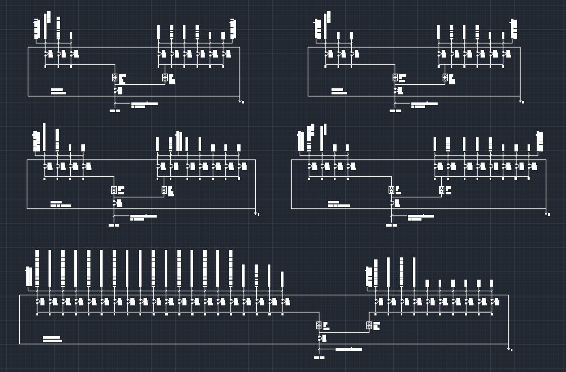
Electrical Single Line Diagram Template (DWG) — LINE DRAW CAD LAB
Electrical Single Line Diagram Part Two Electrical Knowhow

Electrical Single Line Diagram
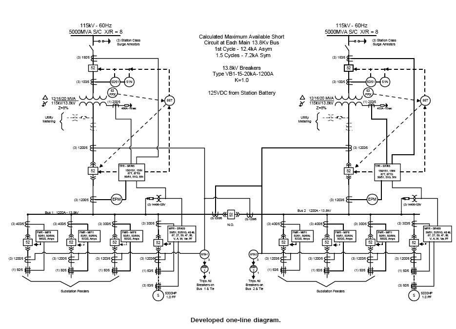
Electrical SingleLine Diagram Electrical OneLine Diagram ETAP

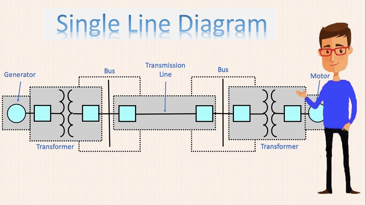
Single Line Diagram Electrical Single Line Diagram How to read
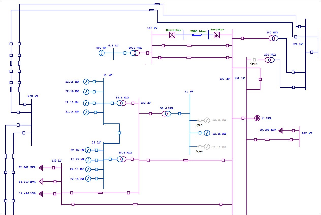
Single Line Diagram Of Electric Power System

Single Line Diagram Electrical Drawing GIS Substation YouTube
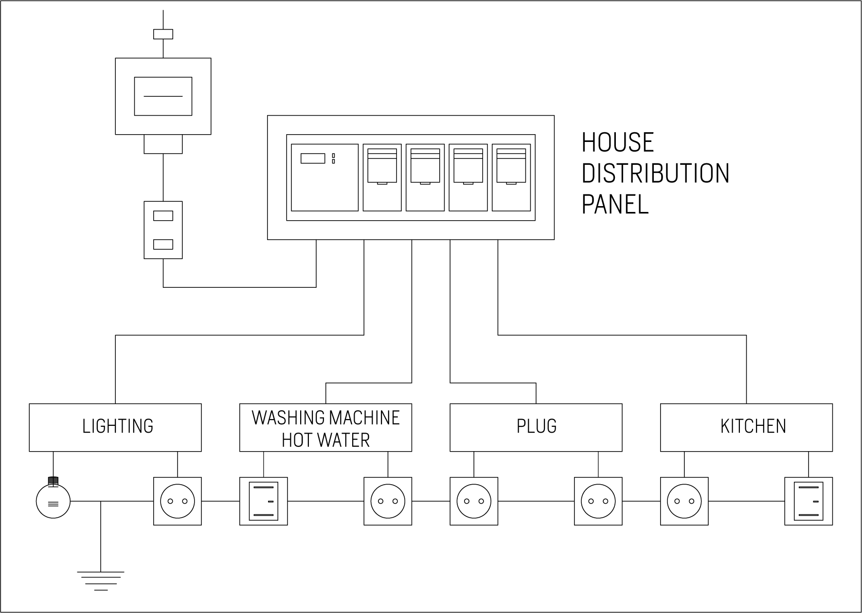
Electrical Drawings
Singleline diagram How to represent the electrical installation of a
Electrical SingleLine Diagram Electrical OneLine Diagram ETAP
A New Feature Preview Only Services Electrical Ladder Diagram Rung Numbering.
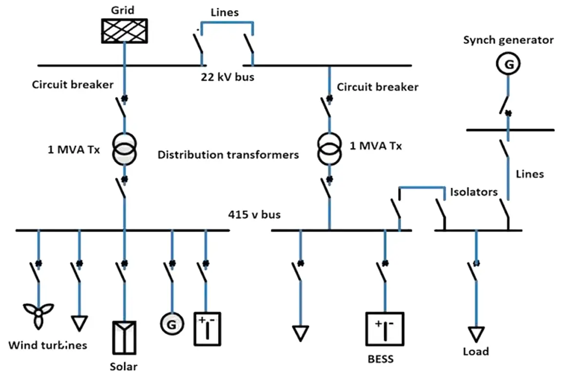
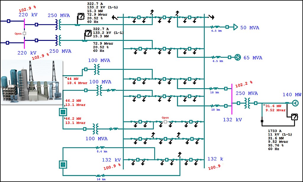
A Single Line Diagram Is A Graphical Representation Of An Electrical Power System Or Grid Using Standard Electrical Symbols.
One Of The Key Tools In Developing And Documenting An Electrical Power System Is The Single Line Diagram (Shortened Sld).
It Shows The Main Components Of The System, Including Generators, Transformers, Circuit Breakers, Meters, And Other Equipment.
Related Post: