Electrical Engineering Drawing
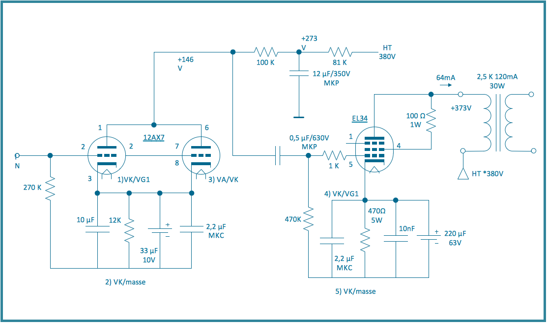
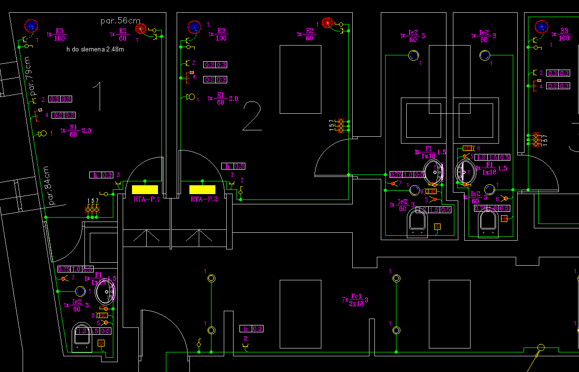
Electrical Engineering Drawing - These electrical circuits are represented by lines to represent wires and symbols or icons to represent electrical and electronic components. Typical electrical drawing symbols and conventions. Basics 18 embedded conduit drawing : In electrical and electronics engineering, we use different types of drawings or diagrams to represent a certain electrical system or circuit. It also explains the various steps involved in the development Basics 19 instrument loop diagram : Schematic drawings, also known as electrical or circuit diagrams, are essential tools for understanding and designing electrical circuits. Basics 17 tray & conduit layout drawing : Electrical drawings are technical documents that depict and notate designs for electrical systems. Use visio to create electrical engineering diagrams, including basic electrical, circuits and logic, systems, and more. Mastering schematic drawing is a fundamental skill for field engineers, allowing them to effectively. Schematic drawings, also known as electrical or circuit diagrams, are essential tools for understanding and designing electrical circuits. Basics 18 embedded conduit drawing : And fabrication, construction, and architectural drawings. Electrical drawings are technical documents that depict and notate designs for electrical systems. An electrical drawing is a type of technical drawing that shows information about power, lighting, and communication for an engineering or architectural project. Use visio to create electrical engineering diagrams, including basic electrical, circuits and logic, systems, and more. Basics 19 instrument loop diagram : Basics 17 tray & conduit layout drawing : These electrical circuits are represented by lines to represent wires and symbols or icons to represent electrical and electronic components. And fabrication, construction, and architectural drawings. In particular, you will understand how to read and interpret a wide variety of electrical diagrams and plans, and how to use them together for analysis and repair. Basics 18 embedded conduit drawing : Learn how to create and interpret various types of electrical drawings with essential symbols and notations for accurate and efficient. Basics 17 tray & conduit layout drawing : In particular, you will understand how to read and interpret a wide variety of electrical diagrams and plans, and how to use them together for analysis and repair. Basics 18 embedded conduit drawing : Electrical drawings are essential tools in the design, installation, and maintenance of electrical systems. The handbook includes information. It also explains the various steps involved in the development Basics 19 instrument loop diagram : Electrical drawings are technical documents that depict and notate designs for electrical systems. In electrical and electronics engineering, we use different types of drawings or diagrams to represent a certain electrical system or circuit. And fabrication, construction, and architectural drawings. Basics 18 embedded conduit drawing : Typical electrical drawing symbols and conventions. It also explains the various steps involved in the development Schematic drawings, also known as electrical or circuit diagrams, are essential tools for understanding and designing electrical circuits. In electrical and electronics engineering, we use different types of drawings or diagrams to represent a certain electrical system or. These electrical circuits are represented by lines to represent wires and symbols or icons to represent electrical and electronic components. Electrical drawings are technical documents that depict and notate designs for electrical systems. Schematic drawings, also known as electrical or circuit diagrams, are essential tools for understanding and designing electrical circuits. Typical electrical drawing symbols and conventions. In electrical drawings,. Electrical drawings are essential tools in the design, installation, and maintenance of electrical systems. These electrical circuits are represented by lines to represent wires and symbols or icons to represent electrical and electronic components. Basics 19 instrument loop diagram : The handbook includes information on engineering fluid drawings and prints; In particular, you will understand how to read and interpret. And fabrication, construction, and architectural drawings. Basics 17 tray & conduit layout drawing : The handbook includes information on engineering fluid drawings and prints; Schematic drawings, also known as electrical or circuit diagrams, are essential tools for understanding and designing electrical circuits. In particular, you will understand how to read and interpret a wide variety of electrical diagrams and plans,. Schematic drawings, also known as electrical or circuit diagrams, are essential tools for understanding and designing electrical circuits. Mastering schematic drawing is a fundamental skill for field engineers, allowing them to effectively. It also explains the various steps involved in the development Learn how to create and interpret various types of electrical drawings with essential symbols and notations for accurate. Learn how to create and interpret various types of electrical drawings with essential symbols and notations for accurate and efficient electrical design. Electrical drawings are technical documents that depict and notate designs for electrical systems. Use visio to create electrical engineering diagrams, including basic electrical, circuits and logic, systems, and more. Basics 18 embedded conduit drawing : Basics 19 instrument. In particular, you will understand how to read and interpret a wide variety of electrical diagrams and plans, and how to use them together for analysis and repair. Use visio to create electrical engineering diagrams, including basic electrical, circuits and logic, systems, and more. Schematic drawings, also known as electrical or circuit diagrams, are essential tools for understanding and designing. Basics 18 embedded conduit drawing : Electrical drawings are technical documents that depict and notate designs for electrical systems. Schematic drawings, also known as electrical or circuit diagrams, are essential tools for understanding and designing electrical circuits. It also explains the various steps involved in the development Learn how to create and interpret various types of electrical drawings with essential symbols and notations for accurate and efficient electrical design. Use visio to create electrical engineering diagrams, including basic electrical, circuits and logic, systems, and more. The handbook includes information on engineering fluid drawings and prints; In electrical and electronics engineering, we use different types of drawings or diagrams to represent a certain electrical system or circuit. These electrical circuits are represented by lines to represent wires and symbols or icons to represent electrical and electronic components. Typical electrical drawing symbols and conventions. Basics 17 tray & conduit layout drawing : And fabrication, construction, and architectural drawings. In particular, you will understand how to read and interpret a wide variety of electrical diagrams and plans, and how to use them together for analysis and repair. In electrical drawings, every type of component and connection has its own specialized symbol—and every detail matters.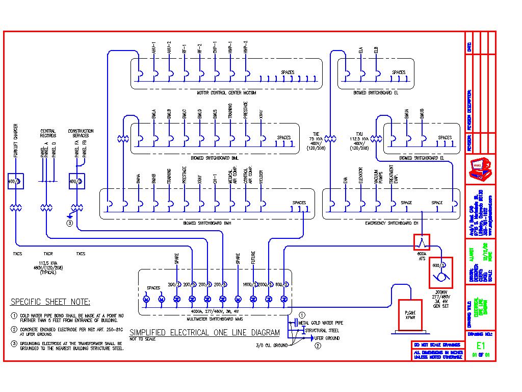
Electrical Drawing at GetDrawings Free download

ARCXEN CAD Design Studio Electrical Engineering Drawings
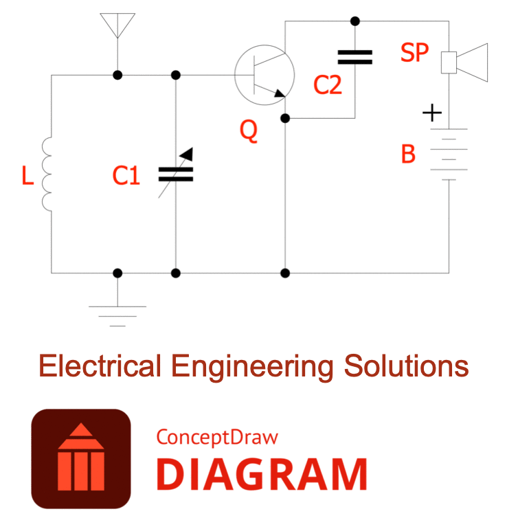
Valuable Additions to Industrial Engineering Area in ConceptDraw Solutions

ARCXEN CAD Design Studio Electrical Engineering Drawings
Electrical Engineer Drawing at GetDrawings Free download
Electrical Engineering Drawing at Explore
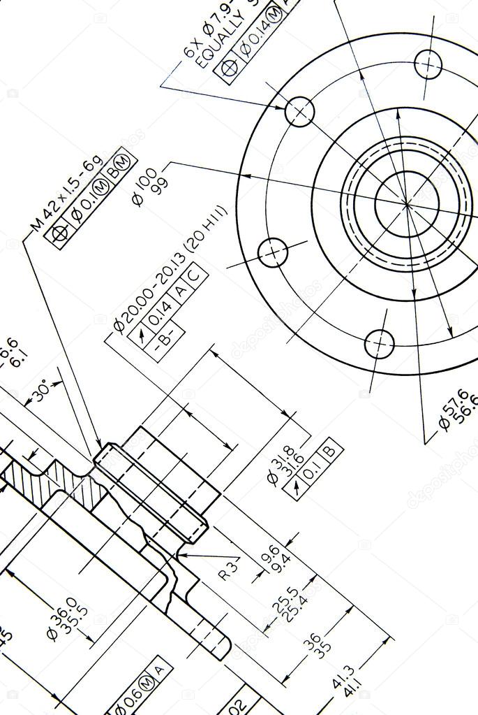
Engineering drawing — Stock Photo © ruhaizal 22857508
Electrical Engineering
Electrical Engineer Drawing at GetDrawings Free download
Electrical Designing and Drafting Bundle (Two Courses) EEP Academy
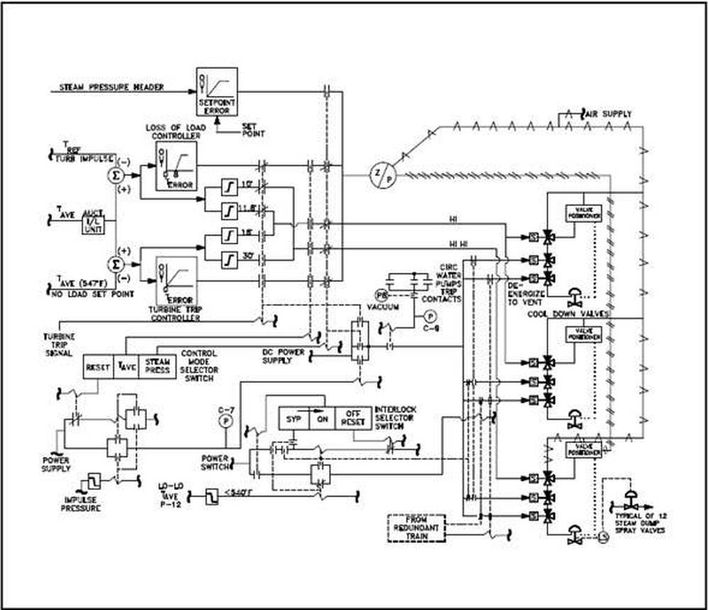
Basics 19 Instrument Loop Diagram :
Mastering Schematic Drawing Is A Fundamental Skill For Field Engineers, Allowing Them To Effectively.
An Electrical Drawing Is A Type Of Technical Drawing That Shows Information About Power, Lighting, And Communication For An Engineering Or Architectural Project.
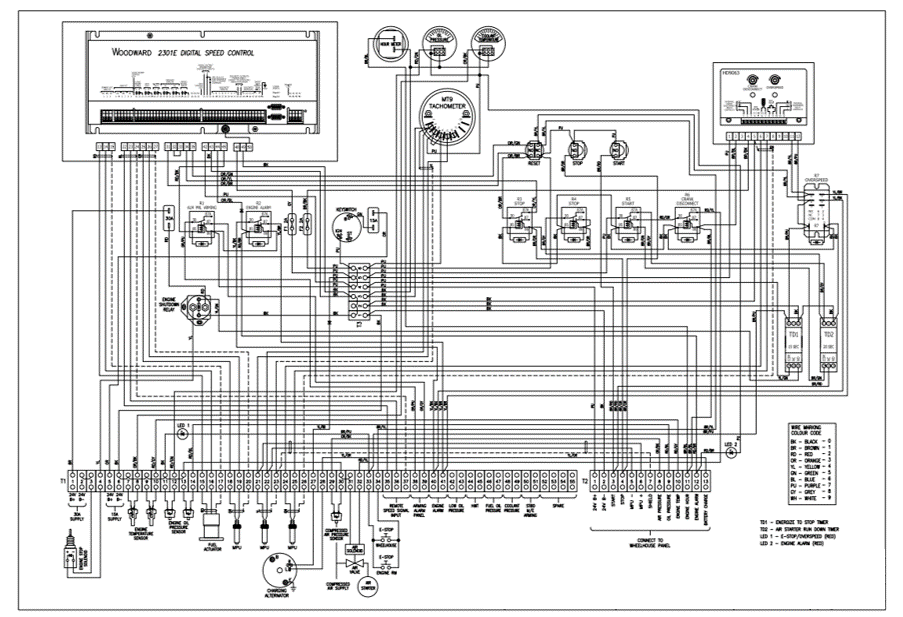
Electrical Drawings Are Essential Tools In The Design, Installation, And Maintenance Of Electrical Systems.
Related Post: