Drawing Symbols Engineering
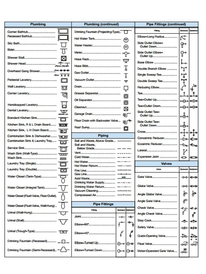
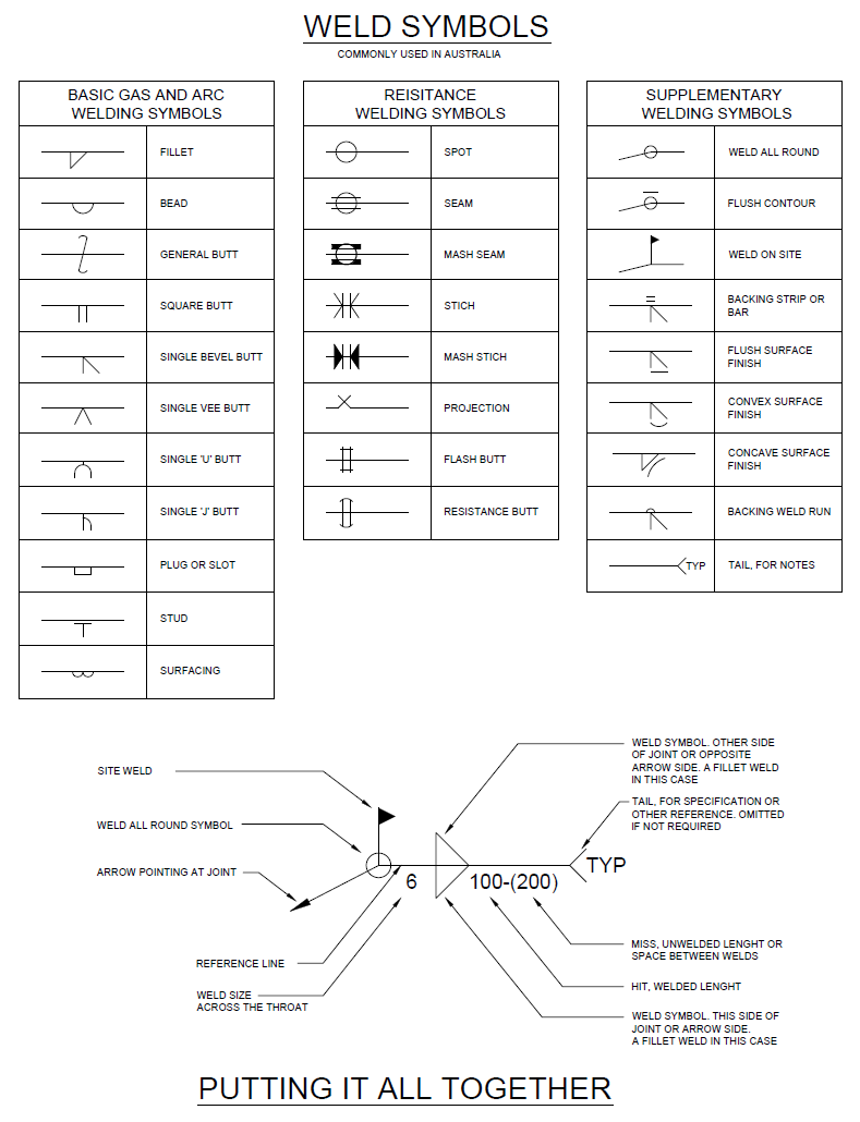
Drawing Symbols Engineering - The following is a list of symbols that are commonly found in engineering drawings: Engineering drawings, also known as blueprints or mechanical drawings, provide a comprehensive outline that goes beyond a simple drawing. Milestone plm solutions offers cad, cam & fea services for. Basic types of symbols used in engineering drawings are countersink, counterbore, spotface, depth, radius,. 262 rows engineering drawing abbreviations and symbols are used to communicate and. This guide offers a comprehensive overview of the most common symbols used in technical drawings, spanning multiple disciplines including mechanical, electrical, and architectural. Learn the basics of how to read engineering drawing symbols for p&id, pfd, and mechanical drawings. Learn about the symbols and concepts of geometric dimensioning and tolerancing (gd&t) with this convenient guide. Learn the meaning and usage of common symbols in engineering drawings, such as radius, diameter, square, thickness, chamfer, and more. The issue date is provided to assist the user in determining the most recent revision. See examples and tips for dispelling. Milestone plm solutions offers cad, cam & fea services for. This course covers the anatomy, types, views and. Engineering drawings, also known as blueprints or mechanical drawings, provide a comprehensive outline that goes beyond a simple drawing. Download the free wall chart and click on the links to explore each gd&t symbol in detail. This guide offers a comprehensive overview of the most common symbols used in technical drawings, spanning multiple disciplines including mechanical, electrical, and architectural. Learn the basics of engineering symbology, prints and drawings from the u.s. The following is a list of symbols that are commonly found in engineering drawings: Learn the meaning and usage of common symbols in engineering drawings, such as radius, diameter, square, thickness, chamfer, and more. They contain specific details and. Engineering drawings, also known as blueprints or mechanical drawings, provide a comprehensive outline that goes beyond a simple drawing. The issue date is provided to assist the user in determining the most recent revision. Find out the meaning and function of different symbols, lines, views, and. This guide offers a comprehensive overview of the most common symbols used in technical. Learn how to create and use geometric dimensioning and tolerancing symbols, common architectural symbols, piping symbols, and electrical symbols in autocad. This course covers the anatomy, types, views and. See examples and tips for dispelling. Download the free wall chart and click on the links to explore each gd&t symbol in detail. Learn the meaning and usage of common symbols. Learn the basics of engineering symbology, prints and drawings from the u.s. See examples and tips for dispelling. Engineering drawings are the industry's means of communicating detailed and accurate information on how to fabricate, assemble, troubleshoot, repair, and operate a piece of. This course covers the anatomy, types, views and. Drawings are comprised of symbols and lines that represent components. The kennedy space center (ksc) engineering drawing practices, volume i of ii, aerospace and ground support equipment, is the official source for the requirements and interpretations to be. Engineering drawings are the industry's means of communicating detailed and accurate information on how to fabricate, assemble, troubleshoot, repair, and operate a piece of. Learn the meanings and uses of various symbols. This guide offers a comprehensive overview of the most common symbols used in technical drawings, spanning multiple disciplines including mechanical, electrical, and architectural. Learn about the symbols and concepts of geometric dimensioning and tolerancing (gd&t) with this convenient guide. The kennedy space center (ksc) engineering drawing practices, volume i of ii, aerospace and ground support equipment, is the official source. They contain specific details and. Learn the basics of how to read engineering drawing symbols for p&id, pfd, and mechanical drawings. Milestone plm solutions offers cad, cam & fea services for. The kennedy space center (ksc) engineering drawing practices, volume i of ii, aerospace and ground support equipment, is the official source for the requirements and interpretations to be. Learn. Milestone plm solutions offers cad, cam & fea services for. See examples and tips for dispelling. This guide offers a comprehensive overview of the most common symbols used in technical drawings, spanning multiple disciplines including mechanical, electrical, and architectural. Learn about the symbols and concepts of geometric dimensioning and tolerancing (gd&t) with this convenient guide. The kennedy space center (ksc). Learn about the symbols and concepts of geometric dimensioning and tolerancing (gd&t) with this convenient guide. The following is a list of symbols that are commonly found in engineering drawings: See examples and tips for dispelling. They contain specific details and. Learn the basics of engineering symbology, prints and drawings from the u.s. They contain specific details and. This page provides a pdf copy of the traffic engineering signing and marking standard drawings. Engineering drawings, also known as blueprints or mechanical drawings, provide a comprehensive outline that goes beyond a simple drawing. Milestone plm solutions offers cad, cam & fea services for. See examples and tips for dispelling. 262 rows engineering drawing abbreviations and symbols are used to communicate and. They contain specific details and. Engineering drawings, also known as blueprints or mechanical drawings, provide a comprehensive outline that goes beyond a simple drawing. The issue date is provided to assist the user in determining the most recent revision. Learn the basics of engineering symbology, prints and drawings. Basic types of symbols used in engineering drawings are countersink, counterbore, spotface, depth, radius,. Drawings are comprised of symbols and lines that represent components or systems. The following is a list of symbols that are commonly found in engineering drawings: Learn how to create and use geometric dimensioning and tolerancing symbols, common architectural symbols, piping symbols, and electrical symbols in autocad. This page provides a pdf copy of the traffic engineering signing and marking standard drawings. Milestone plm solutions offers cad, cam & fea services for. Learn the basics of engineering symbology, prints and drawings from the u.s. The kennedy space center (ksc) engineering drawing practices, volume i of ii, aerospace and ground support equipment, is the official source for the requirements and interpretations to be. Engineering drawings, also known as blueprints or mechanical drawings, provide a comprehensive outline that goes beyond a simple drawing. 262 rows engineering drawing abbreviations and symbols are used to communicate and. Find out the meaning and function of different symbols, lines, views, and. Department of energy fundamentals handbook. Learn the meaning and usage of common symbols in engineering drawings, such as radius, diameter, square, thickness, chamfer, and more. Learn the basics of how to read engineering drawing symbols for p&id, pfd, and mechanical drawings. This guide offers a comprehensive overview of the most common symbols used in technical drawings, spanning multiple disciplines including mechanical, electrical, and architectural. This course covers the anatomy, types, views and.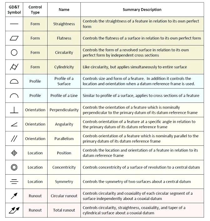
Engineering Drawing Symbols

Civil Engineering Drawing Symbols And Their Meanings at PaintingValley
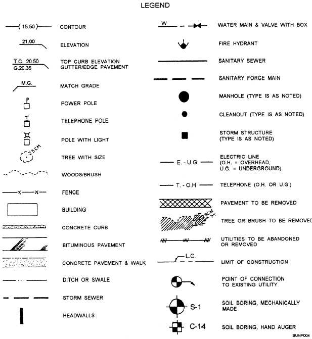
Civil Engineering Drawing Symbols And Their Meanings at PaintingValley
Civil Engineering Drawing Symbols And Their Meanings at PaintingValley
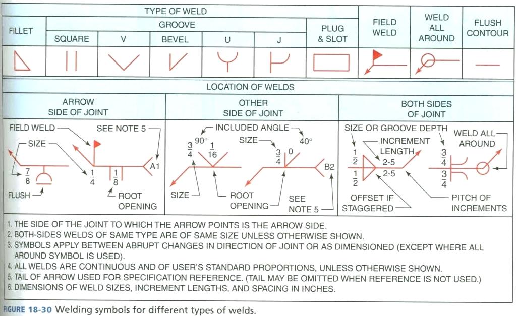
Basic Engineering Drawing Symbols

how to read mechanical engineering drawing symbols Wiring Work

Symbols Engineering, Drawing APK for Android Download
Civil Engineering Drawing Symbols And Their Meanings at PaintingValley
Civil Engineering Drawing Symbols And Their Meanings at PaintingValley
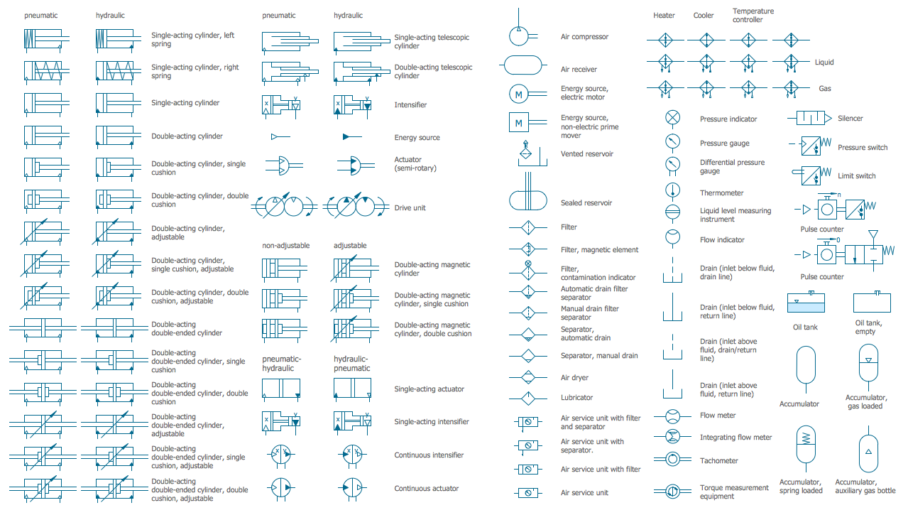
Mechanical Engineering Drawing Symbols
They Contain Specific Details And.
The Issue Date Is Provided To Assist The User In Determining The Most Recent Revision.
See Examples And Tips For Dispelling.
Download The Free Wall Chart And Click On The Links To Explore Each Gd&T Symbol In Detail.
Related Post: