Chamfer Callout Drawing
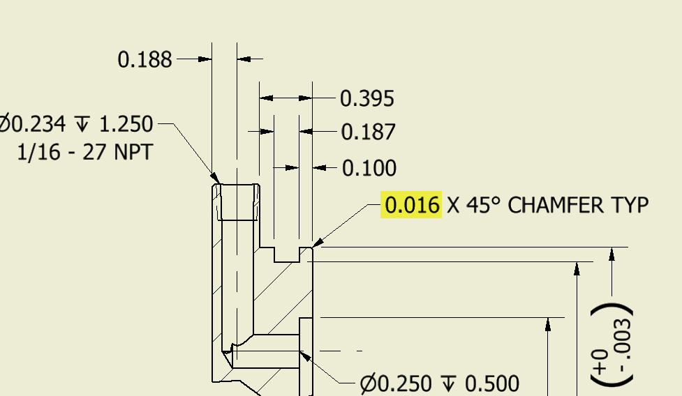
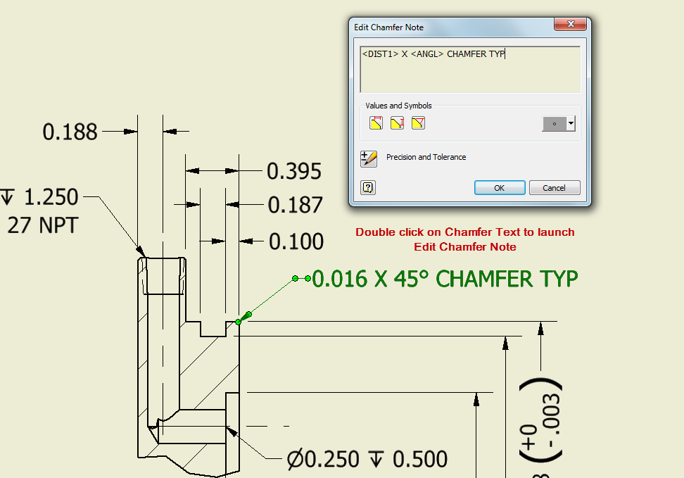
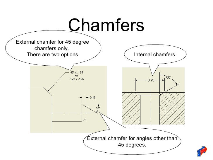
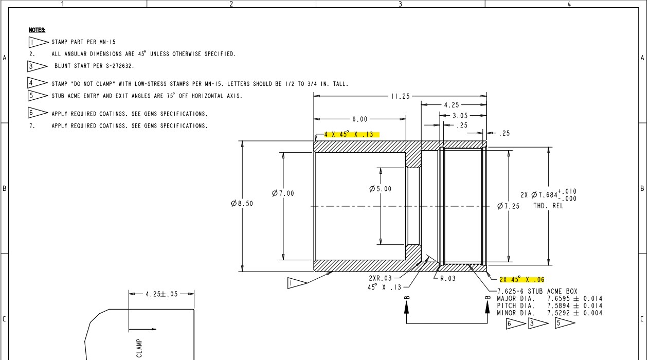
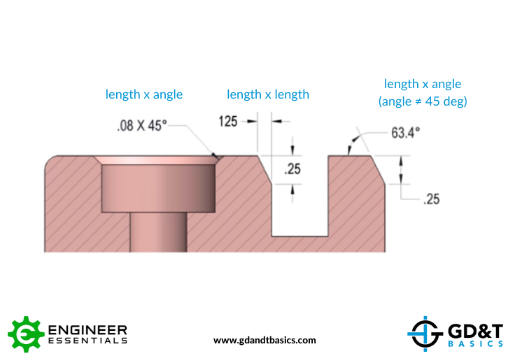
Chamfer Callout Drawing - Optical drawings provide a precise definition of your optic for fabrication. In addition to the usual dimension display properties, chamfer dimensions have their own options for leader display, text display, and x display. For example, the part below had a.09x45deg chamfer added to a. You can dimension chamfers in drawings. You can dimension chamfers in drawings. Specifying a chamfer on the print, either by using a local note or by using linear and angular dimensions. If an angle other than 45 degrees is dimensioned,. Is the correct callout for this 2x 0.031 x 45° or does each chamfer need to be noted individually. In addition to the usual dimension display properties, chamfer dimensions have their own options for leader display, text display, and x display. With the drawing above we have 4. To make the dimension callout like your picture, select the perpindicular option on the chamfer dimensioning tool dropdown menu. Chamfers can be dimensioned in two ways, either by calling out the length by angle, or calling out the length by length. If an angle other than 45 degrees is dimensioned,. Then select one of the lines at the end of your chamfer,. Specifying a chamfer on the print, either by using a local note or by using linear and angular dimensions. In addition to the usual dimension display properties, chamfer dimensions have their own options for leader display, text display, and x display. Optical drawings provide a precise definition of your optic for fabrication. You can dimension chamfers in drawings. Standards allow for a common language to be used between you and the optician so there is no confusion regarding. Master the art of chamfer callout drawings with our expert guide. You can dimension chamfers in drawings. Have you ever seen a 1x1 chamfer called out as c1 on a drawing? You can dimension chamfers in drawings. Specifying a chamfer on the print, either by using a local note or by using linear and angular dimensions. In addition to the usual dimension display properties, chamfer dimensions have their own options for. If an angle other than 45 degrees is dimensioned,. Is the correct callout for this 2x 0.031 x 45° or does each chamfer need to be noted individually. In addition to the usual dimension display properties, chamfer dimensions have their own options for leader display, text display, and x display. With the drawing above we have 4. You can dimension. Have you ever seen a 1x1 chamfer called out as c1 on a drawing? For example, the part below had a.09x45deg chamfer added to a. Standards allow for a common language to be used between you and the optician so there is no confusion regarding. You can dimension chamfers in drawings. Then select one of the lines at the end. Is the correct callout for this 2x 0.031 x 45° or does each chamfer need to be noted individually. You can dimension chamfers in drawings. To make the dimension callout like your picture, select the perpindicular option on the chamfer dimensioning tool dropdown menu. I'm running into issues when i try to dimension chamfers that were added to edges that. In addition to the usual dimension display properties, chamfer dimensions have their own options for leader display, text display, and x display. Is the correct callout for this 2x 0.031 x 45° or does each chamfer need to be noted individually. Master the art of chamfer callout drawings with our expert guide. Specifying a chamfer on the print, either by. Master the art of chamfer callout drawings with our expert guide. Optical drawings provide a precise definition of your optic for fabrication. In addition to the usual dimension display properties, chamfer dimensions have their own options for leader display, text display, and x display. Then select one of the lines at the end of your chamfer,. Specifying a chamfer on. For example, the part below had a.09x45deg chamfer added to a. To make the dimension callout like your picture, select the perpindicular option on the chamfer dimensioning tool dropdown menu. I have a cylindrical part with a chamfer at each end. With the drawing above we have 4. In addition to the usual dimension display properties, chamfer dimensions have their. Have you ever seen a 1x1 chamfer called out as c1 on a drawing? I'm running into issues when i try to dimension chamfers that were added to edges that were not perpendicular. Chamfers can be dimensioned in two ways, either by calling out the length by angle, or calling out the length by length. Often prints that are delivered. Often prints that are delivered using standard gd&t call out dimensions for chamfers using a diameter value and not a specific size. Then select one of the lines at the end of your chamfer,. Specifying a chamfer on the print, either by using a local note or by using linear and angular dimensions. Standards allow for a common language to. Learn the 5 essential ways to create precise and effective chamfer callouts in technical drawings, including methods for. In addition to the usual dimension display properties, chamfer dimensions have their own options for leader display, text display, and x display. In addition to the usual dimension display properties, chamfer dimensions have their own options for leader display, text display, and. You can dimension chamfers in drawings. With the drawing above we have 4. I'm running into issues when i try to dimension chamfers that were added to edges that were not perpendicular. In addition to the usual dimension display properties, chamfer dimensions have their own options for leader display, text display, and x display. Is the correct callout for this 2x 0.031 x 45° or does each chamfer need to be noted individually. If an angle other than 45 degrees is dimensioned,. Optical drawings provide a precise definition of your optic for fabrication. If a chamfer is 45 n, the leg distance is the same on both sides. You can dimension chamfers in drawings. Then select one of the lines at the end of your chamfer,. In addition to the usual dimension display properties, chamfer dimensions have their own options for leader display, text display, and x display. You can dimension chamfers in drawings. Specifying a chamfer on the print, either by using a local note or by using linear and angular dimensions. Master the art of chamfer callout drawings with our expert guide. Learn the 5 essential ways to create precise and effective chamfer callouts in technical drawings, including methods for. In addition to the usual dimension display properties, chamfer dimensions have their own options for leader display, text display, and x display.Inventor Ability to change the decimal places in the call out of the
Dimensioning standards

Adding a Chamfer Dimension YouTube

SolidWorks Tutorial How to Add Chamfer Dimension In Solidworks Drawing
Solved Multiple chamfers on drawings PTC Community
Solved Chamfers on Drawings Autodesk Community
Chamfer Dimensioning GD&T Basics
Inventor Ability to change the decimal places in the call out of the

Practice 2 Autocad Drawing using Chamfer Command YouTube
Solved Chamfers on Drawings Autodesk Community
For Example, The Part Below Had A.09X45Deg Chamfer Added To A.
To Make The Dimension Callout Like Your Picture, Select The Perpindicular Option On The Chamfer Dimensioning Tool Dropdown Menu.
Standards Allow For A Common Language To Be Used Between You And The Optician So There Is No Confusion Regarding.
Have You Ever Seen A 1X1 Chamfer Called Out As C1 On A Drawing?
Related Post: