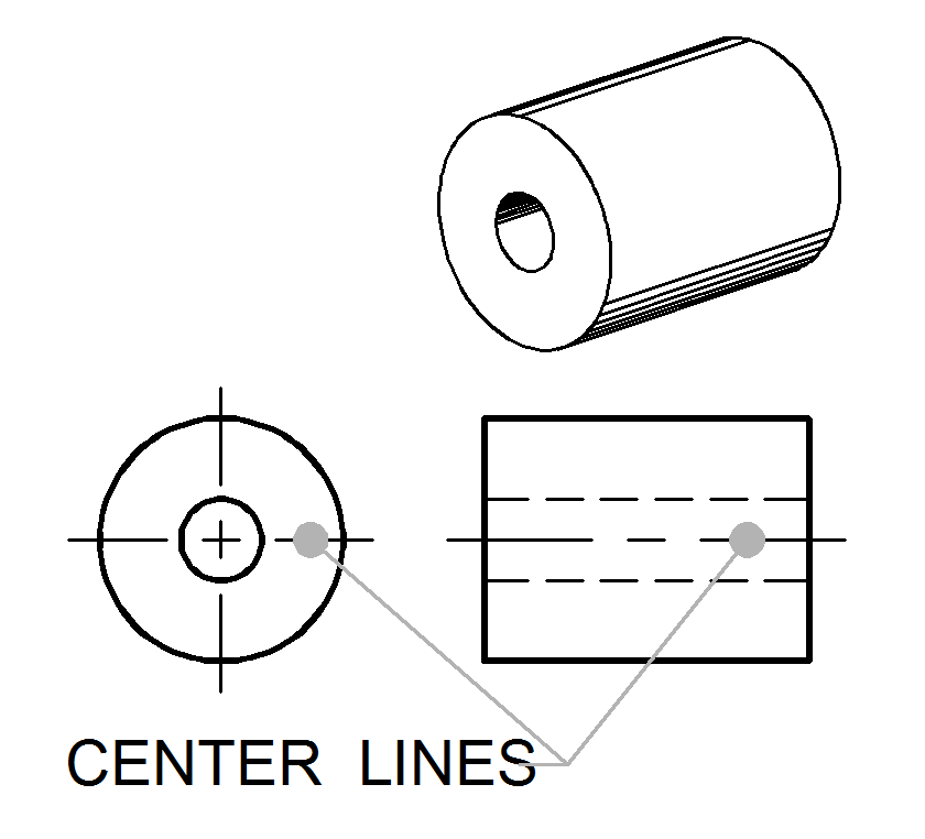
Center Lines In Engineering Drawing
Center Lines In Engineering Drawing - The lines are thin and are usually. All professional engineers and architects involved in the design of the structure are to. Computer aided drafting (cad) details and notes are provided to ensure a consistent and up to date design. Lane dimensions are for informational purposes, all private and public owned utility lines shall maintain a 6' (min.) outside td outside. Questions about using centerlines are so common that we wanted to post some information about why they are used, and how they impact more than just your hole to hole. They serve as a reference for dimensions and alignment,. Center lines are used to indicate the center of a circle, arc, or any symmetrical object. Center lines in an engineering drawing show the center of a round or cylindrical shape. The meaning of a center line is normally determined by how it is used. Center lines when used, represent axes, center points or center planes of symmetrical parts and features and also bolt. Long dashes are used to begin. A center line plan is crucial for accurately placing structural ele. Center lines in an engineering drawing show the center of a round or cylindrical shape. The line is drawn using a thin line with alternating long and short dashes. They serve as a reference for dimensions and alignment,. Center lines when used, represent axes, center points or center planes of symmetrical parts and features and also bolt. All professional engineers and architects involved in the design of the structure are to. Over 1,000,000 customersfree supportthousands of templatesimport & export visio The meaning of a center line is normally determined by how it is used. Center lines are used to indicate the center of a circle, arc, or any symmetrical object. The meaning of a center line is normally determined by how it is used. Long dashes are used to begin. All professional engineers and architects involved in the design of the structure are to. Center lines are reference lines used in technical drawing to indicate the center of an object or feature. Center lines are imaginary lines used in engineering. Computer aided drafting (cad) details and notes are provided to ensure a consistent and up to date design. Center lines when used, represent axes, center points or center planes of symmetrical parts and features and also bolt. Long dashes are used to begin. Center lines in an engineering drawing show the center of a round or cylindrical shape. They help. Computer aided drafting (cad) details and notes are provided to ensure a consistent and up to date design. Lane dimensions are for informational purposes, all private and public owned utility lines shall maintain a 6' (min.) outside td outside. Data must be delineated into the drawings by notes or graphics as part of the original tracings or masters. Center lines. They serve as a reference for dimensions and alignment,. Over 1,000,000 customersfree supportthousands of templatesimport & export visio Center lines when used, represent axes, center points or center planes of symmetrical parts and features and also bolt. The meaning of a center line is normally determined by how it is used. Specifications and an approved materials list will assist the. The line is drawn using a thin line with alternating long and short dashes. Long dashes are used to begin. Center lines when used, represent axes, center points or center planes of symmetrical parts and features and also bolt. Data must be delineated into the drawings by notes or graphics as part of the original tracings or masters. Over 1,000,000. The diagonal lines on the section drawing are used to indicate the area that has been theoretically cut. They serve as a reference for dimensions and alignment,. Computer aided drafting (cad) details and notes are provided to ensure a consistent and up to date design. Long dashes are used to begin. Center lines (figure \(\pageindex{5}\)) are used in drawings for. The line is drawn using a thin line with alternating long and short dashes. Data must be delineated into the drawings by notes or graphics as part of the original tracings or masters. The meaning of a center line is normally determined by how it is used. Center lines in an engineering drawing show the center of a round or. Center lines are used to indicate the center of a circle, arc, or any symmetrical object. They help to establish symmetry and provide a visual guide for the alignment and. The diagonal lines on the section drawing are used to indicate the area that has been theoretically cut. Lane dimensions are for informational purposes, all private and public owned utility. They help to establish symmetry and provide a visual guide for the alignment and. Specifications and an approved materials list will assist the contractor in. All professional engineers and architects involved in the design of the structure are to. The meaning of a center line is normally determined by how it is used. A center line plan is crucial for. Questions about using centerlines are so common that we wanted to post some information about why they are used, and how they impact more than just your hole to hole. The meaning of a center line is normally determined by how it is used. Specifications and an approved materials list will assist the contractor in. Center lines are imaginary lines. The line is drawn using a thin line with alternating long and short dashes. Center lines in an engineering drawing show the center of a round or cylindrical shape. A center line plan is crucial for accurately placing structural ele. The lines are thin and are usually. Center lines when used, represent axes, center points or center planes of symmetrical parts and features and also bolt. Center lines are reference lines used in technical drawing to indicate the center of an object or feature. Specifications and an approved materials list will assist the contractor in. All professional engineers and architects involved in the design of the structure are to. Questions about using centerlines are so common that we wanted to post some information about why they are used, and how they impact more than just your hole to hole. Center lines (figure \(\pageindex{5}\)) are used in drawings for several different applications. Data must be delineated into the drawings by notes or graphics as part of the original tracings or masters. Long dashes are used to begin. Computer aided drafting (cad) details and notes are provided to ensure a consistent and up to date design. Center lines are imaginary lines used in engineering drawings to indicate the centers of circles, arcs, and symmetrical objects. The diagonal lines on the section drawing are used to indicate the area that has been theoretically cut. Center lines are used to indicate the center of a circle, arc, or any symmetrical object.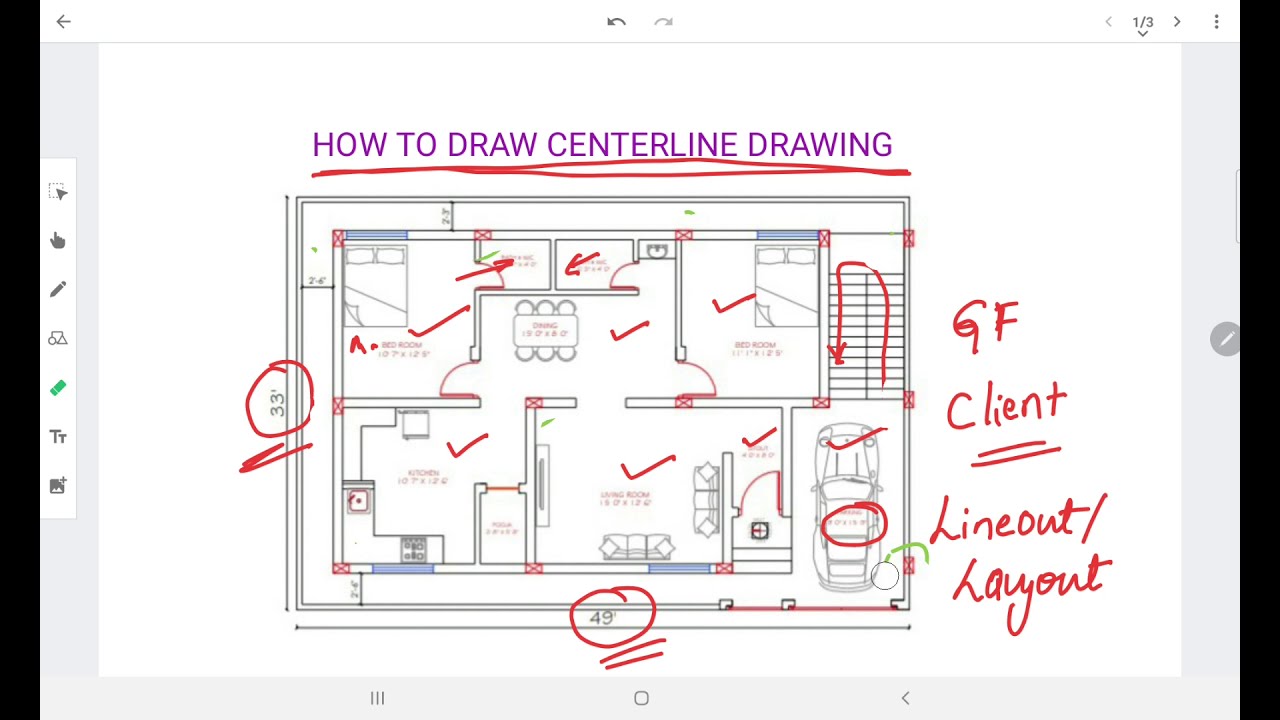
HOW TO PREPARE CENTERLINE DRAWING YouTube

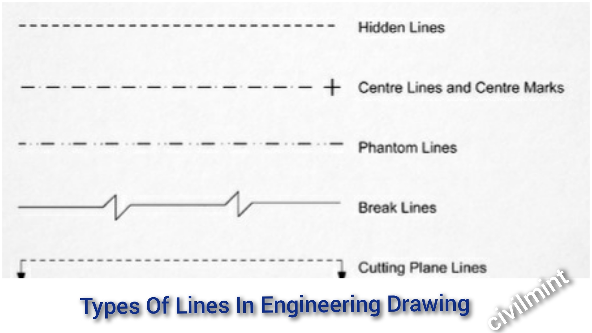
Types of Lines in Engineering/ Technical Drawings and Their Uses What

SIEMENS NX DRAFTING 7 CENTERLINE (Circular, Bolt Circle, Symmetrical
Engineering Drawing Centerline Symbol at stevenfloydo blog

Center Lines

2020 Drawing Center Lines for an Orthographic Drawing YouTube
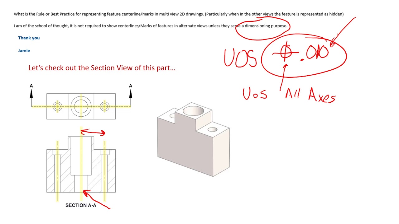
Centerlines on Engineering Drawings and how they should be used
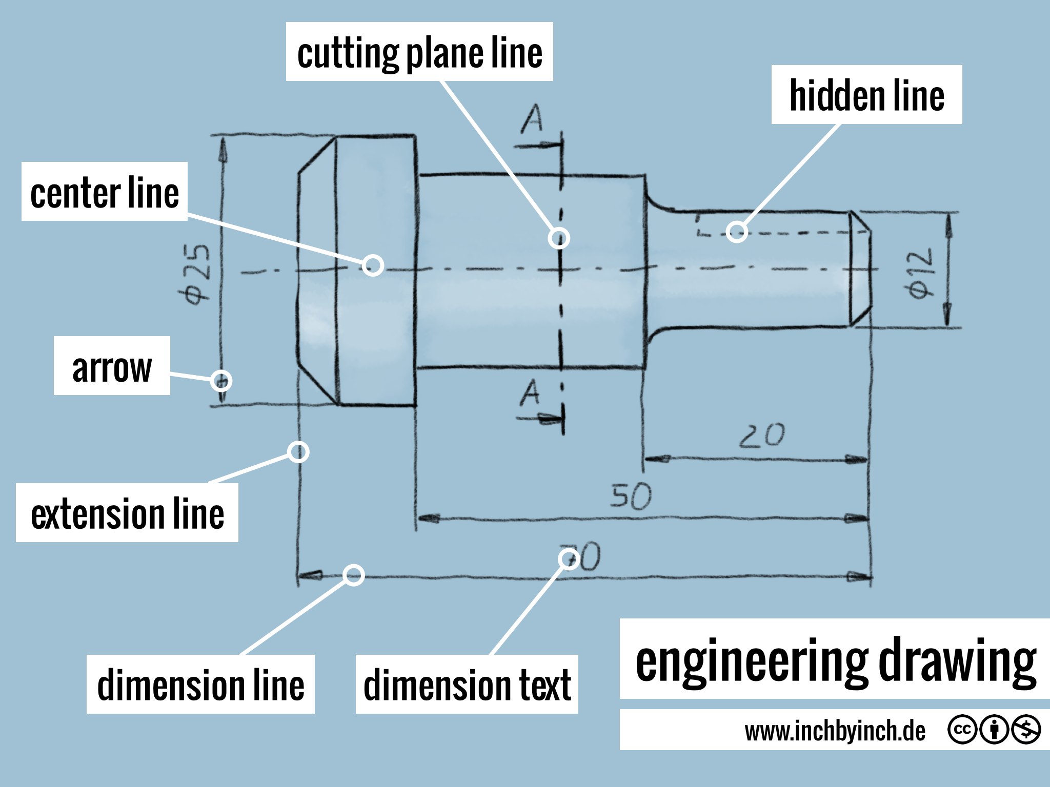
INCH Technical English engineering drawing
Center Lines ToolNotes

Classifications of Civil Engineering Drawings and Interpreting
Lane Dimensions Are For Informational Purposes, All Private And Public Owned Utility Lines Shall Maintain A 6' (Min.) Outside Td Outside.
They Help To Establish Symmetry And Provide A Visual Guide For The Alignment And.
They Serve As A Reference For Dimensions And Alignment,.
The Kennedy Space Center (Ksc) Engineering Drawing Practices, Volume I Of Ii, Aerospace And Ground Support Equipment, Is The Official Source For The Requirements And Interpretations To Be.
Related Post: